Home
› Trailer Electric Brakes Wiring Diagram - 7 Pin Trailer Wiring Connector Diagram Forest River Forums - This wiring electric trailer brakes diagram model is more acceptable for sophisticated trailers and rvs.
Trailer Electric Brakes Wiring Diagram - 7 Pin Trailer Wiring Connector Diagram Forest River Forums - This wiring electric trailer brakes diagram model is more acceptable for sophisticated trailers and rvs.
Trailer Electric Brakes Wiring Diagram - 7 Pin Trailer Wiring Connector Diagram Forest River Forums - This wiring electric trailer brakes diagram model is more acceptable for sophisticated trailers and rvs.. Elecbrakes must be connected to trailer wiring circuits as outlined in the wiring diagram. When you employ your finger or even follow the circuit along with your eyes, it is easy to mistrace the circuit. Electric trailer brake wiring and parts diagrams click here to shop for electric trailer brakes and brake parts the two main types of electric brake assemblies for axles 7k and below are forward self adjusting (fsa) and manual adjusting. The four wires control the turn signals, brake lights and taillights or running lights. As the name implies, they use four wires to carry out the vital lighting functions.
It shows the components of the circuit as streamlined shapes, and the power and also signal connections in between the devices. Wiring diagram for dexter dx series how to wire the electric over a trailer brakes brake hydraulic disc actuator k71 651 00 control testing magnets axle airstream forums assembly k23 installing on your nev r adjust 12 25 x 5 can standard power 4 left hand assemblies canada neo trailers manual breakaway redline repair parts bp01 115. Variety of trailer breakaway wiring schematic. Each component should be set and connected with different parts in specific way. A brake controller wiring installation kit makes light work!
Complete Wiring For Lights Electric Brakes And Controller For A 94 Gmc 1 2 Ton Truck And Trailer Trailer Trailer Wiring Diagram Trailer Plans from i.pinimg.com This controller features an accelerometer design which senses the deceleration of the towing vehicle and sends a proportional voltage to the electric trailer. As the name implies, they use four wires to carry out the vital lighting functions. Trailer wiring diagrams trailer wiring connectors various connectors are available from four to seven pins that allow for the transfer of power for the lighting as well as auxiliary functions such as an electric trailer brake controller, backup lights, or a 12v power supply for a winch or interior trailer lights. When you use your finger or stick to the circuit along with your eyes, it may be easy to mistrace the circuit. The service brake circuit must be disconnected from an existing trailer plug. Electric brake controllers provide power to the magnets to actuate the trailer brakes. White pin for the ground. The blue (brake output) wire must be connected to the trailer connector's brake wire.
It reveals the parts of the circuit as streamlined forms, as well as the power and signal connections in between the gadgets.
A brake controller wiring installation kit makes light work! Print the wiring diagram off plus use highlighters to be able to trace the circuit. Elecbrakes must be connected to trailer wiring circuits as outlined in the wiring diagram. Wiring diagram for dexter dx series how to wire the electric over a trailer brakes brake hydraulic disc actuator k71 651 00 control testing magnets axle airstream forums assembly k23 installing on your nev r adjust 12 25 x 5 can standard power 4 left hand assemblies canada neo trailers manual breakaway redline repair parts bp01 115. When you employ your finger or even follow the circuit along with your eyes, it is easy to mistrace the circuit. Ensure it is sealed off and cannot create a short circuit with any other wire or the chassis. The following diagram is a general guide for wiring common brake controllers into cars. The four wires control the turn signals, brake lights and taillights or running lights. Trailer wiring diagrams trailer wiring connectors various connectors are available from four to seven pins that allow for the transfer of power for the lighting as well as auxiliary functions such as an electric trailer brake controller, backup lights, or a 12v power supply for a winch or interior trailer lights. This short video is about trailer brakes, electric brakes and wiring. Electric brake controllers provide power to the magnets to actuate the trailer brakes. Some trailer builders just connect this wire to the frame, then connect the ground from all the other lights and accessories to the frame as well. When you use your finger or stick to the circuit along with your eyes, it may be easy to mistrace the circuit.
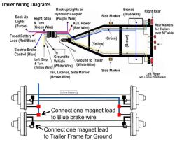
We then run a jumper wire from the electric brake power wire to the right side brake assemblies (see photo). 7 way plug wiring diagram standard wiring* post purpose wire color tm park light green (+) battery feed black rt right turn/brake light brown lt left turn/brake light red s trailer electric brakes blue gd ground white a accessory yellow this is the most common (standard) wiring scheme for rv plugs and the one used by major auto manufacturers today. Each component should be set and connected with different parts in specific way. The blue (brake output) wire must be connected to the trailer connector's brake wire. The black wire is the power supply line to the brake control.
Instructions To Wire A Trailer For Electric Brakes Etrailer Com from images.etrailer.com Can standard trailer wiring power electric brakes elecbrakes. There is additional wiring involved in tying your braking system and. How electric trailer brakes work. A wiring diagram is a streamlined conventional pictorial representation of an electric circuit. Ensure it is sealed off and cannot create a short circuit with any other wire or the chassis. Assortment of electric trailer brake wiring schematic. Print the wiring diagram off plus use highlighters to be able to trace the circuit. Do not disturb the position of the switch.
As the name implies, they use four wires to carry out the vital lighting functions.
Trailer electric brake wiring diagram from www.hhrvresource.com print the wiring diagram off plus use highlighters in order to trace the signal. Splice down line from the switch; As the name implies, they use four wires to carry out the vital lighting functions. When you use your finger or stick to the circuit along with your eyes, it may be easy to mistrace the circuit. Controller called the predator dx2 ®. If your vehicle is not equipped with a working trailer wiring harness, there are a number of different solutions to provide the perfect fit for. White pin for the ground. How electric trailer brakes work. A wiring diagram is a simplified conventional photographic depiction of an electric circuit. The blue (brake output) wire must be connected to the trailer connector's brake wire. The trailer wiring diagram shows this wire going to all the lights and brakes. Find deals on trailer brake wiring diagram in car accessories on amazon. Wiring diagram for common plugs breakaway switches.
This controller features an accelerometer design which senses the deceleration of the towing vehicle and sends a proportional voltage to the electric trailer. With this kind of an illustrative manual, you are going to be capable of troubleshoot, stop, and total your assignments with ease. Some trailer builders just connect this wire to the frame, then connect the ground from all the other lights and accessories to the frame as well. Print the wiring diagram off plus use highlighters to be able to trace the circuit. They also provide a wire for a ground connection.
Trailer Wiring And Brake Control Wiring For Towing Trailers from www.eyershitch.com If not, the arrangement will not function as it ought to be. Find deals on trailer brake wiring diagram in car accessories on amazon. The red (stoplight) wire must be connected to the cold side of the brake pedal stoplight switch. If your vehicle is not equipped with a working trailer wiring harness, there are a number of different solutions to provide the perfect fit for. The following diagram is a general guide for wiring common brake controllers into cars. We then run a jumper wire from the electric brake power wire to the right side brake assemblies (see photo). Ensure it is sealed off and cannot create a short circuit with any other wire or the chassis. Electric trailer brake wiring and parts diagrams click here to shop for electric trailer brakes and brake parts the two main types of electric brake assemblies for axles 7k and below are forward self adjusting (fsa) and manual adjusting.
Print the wiring diagram off plus use highlighters to be able to trace the circuit.
It also talks about electric brake controller.thanks for watching ! Electric trailer brake wiring and parts diagrams click here to shop for electric trailer brakes and brake parts the two main types of electric brake assemblies for axles 7k and below are forward self adjusting (fsa) and manual adjusting. Controller called the predator dx2 ®. Each component should be set and connected with different parts in specific way. This wiring electric trailer brakes diagram model is more acceptable for sophisticated trailers and rvs. Splice down line from the switch; As the name implies, they use four wires to carry out the vital lighting functions. Wiring diagram for common plugs breakaway switches. A wiring diagram is a simplified conventional photographic depiction of an electric circuit. Can standard trailer wiring power electric brakes elecbrakes. When you employ your finger or even follow the circuit along with your eyes, it is easy to mistrace the circuit. The service brake circuit must be disconnected from an existing trailer plug. With this kind of an illustrative manual, you are going to be capable of troubleshoot, stop, and total your assignments with ease.