Home
› Switch Schematic Diagram : The Schematic Diagram Below Shows The Electricity Chegg Com : Transfer switch wiring schematic all diagram schematics.
Switch Schematic Diagram : The Schematic Diagram Below Shows The Electricity Chegg Com : Transfer switch wiring schematic all diagram schematics.
Switch Schematic Diagram : The Schematic Diagram Below Shows The Electricity Chegg Com : Transfer switch wiring schematic all diagram schematics.. 2012 ford focus wiring diagram pdf. Briggs and stratton power products 071068 02 200 amp. R1 = 100ω r2 = 680ω capacitor: Resistors, variable resistors, switches, capacitors, inductors, diodes, voltage sources. Additional 3 way 2 way switch wiring methods.
From/to av jack/switch schematic sound_gnd. Here is the picture of some important symbols in the schematic diagram that represents; Automatic transfer switch schematic diagram wiring diagram m2. Wiring diagrams use standard symbols for wiring devices, usually different from those used on schematic diagrams. This simple touch switch is developed by using 555 timer ic operated as a monostable vibrator.
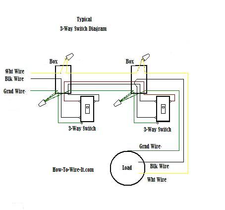
Wiring A 3 Way Switch from www.how-to-wire-it.com R1 = 100ω r2 = 680ω capacitor: Use this infrared toggle switch for wireless switching. I want to do this diagram in latex. I know how to draw rectangles and arrows (basic tikz user) but doing it symmetrically such that the arrow head is in the center of the box consumes a lot of time (usually need to do it on paper first. This schematic diagram is the latest at the time of printing and subject to change without notice. The last circuit was added on thursday, november 28, 2019.please note some adblockers will. Two way switching schematic wiring diagram wire control. The 10k resistor connected across the supply provides a discharge path for the capacitor when power is turned off and is not needed if the power supply already has a bleeder.
An electronic limit switch senses mechanical motion, but does so using light, magnetic.
Diseqc 2.0 switch 4x1 generic schematic diagram. Posted on april 20, 2019april 20, 2019. This simple touch switch is developed by using 555 timer ic operated as a monostable vibrator. R1 = 100ω r2 = 680ω capacitor: This schematic diagram is the latest at the time of printing and subject to change without notice. Wiring diagrams use standard symbols for wiring devices, usually different from those used on schematic diagrams. Switch monostable timer with 555 ic electronic schematic. Light sensitive switch circuit diagram. And we also believe you arrived here were searching for this info, are not you? Use this infrared toggle switch for wireless switching. Chassis harness diagram (under cab to rear) 2010 lhd. I know how to draw rectangles and arrows (basic tikz user) but doing it symmetrically such that the arrow head is in the center of the box consumes a lot of time (usually need to do it on paper first. Oleh admin april 08, 2020 posting komentar.
Usb switch schematic circuit image. 327 daihatsu engine parts diagram. Two of the switches in the package are used to isolate the data path. The 10k resistor connected across the supply provides a discharge path for the capacitor when power is turned off and is not needed if the power supply already has a bleeder. Automatic transfer switch schematic diagram wiring diagram m2.
Toggle Switch Wiring from www.learningaboutelectronics.com R1 = 100ω r2 = 680ω capacitor: From/to av jack/switch schematic sound_gnd. With a pair of 3 way switches either switch can make or break the connection that completes t. The last circuit was added on thursday, november 28, 2019.please note some adblockers will. Diagram 4 wire range schematic diagram full version hd. pdf typical automatic transfer switch diagrams switch socomec diagram: Automatic transfer switch schematic diagram wiring diagram m2. Posted on april 20, 2019april 20, 2019.
Main cab schematic additional switch schematics routed to boc 4700 329.
We attempt to talk about this switching power supply schematic diagram photo in this post simply because based on facts from google engine, it really is one of many top rated queries keyword on google. A circuit diagram with an led resistor and a switch when the switch is closed current flows and the led can illuminate otherwise no current flows. Usb switch schematic circuit image. You need to add ir receiver to electronic device for switching using this circuit. With a pair of 3 way switches either switch can make or break the connection that completes t. Schematic and actual wiring diagram is also provided. Chassis harness diagram (under cab to rear) 2010 lhd. Diseqc 2.0 switch 4x1 generic schematic diagram. 2007 chevy impala serpentine belt diagram. The 10k resistor connected across the supply provides a discharge path for the capacitor when power is turned off and is not needed if the power supply already has a bleeder. 2012 ford focus wiring diagram pdf. The circuit uses a quad analogue switch type 74hc4066. Buffered 2:1 tmds switch ad8193 features.
Resistor r10 and capacitor c7 connected to pin 4 of ic2 prevent false triggering when ic1 provides the supply voltage to ic2 at first clap. A schematic, or schematic power window switch wiring schematic, is usually a illustration of the weather of the method applying abstract, graphic symbols rather than realistic images. R1 = 100ω r2 = 680ω capacitor: Here is the picture of some important symbols in the schematic diagram that represents; Schematic diagram a schematic diagram is a graphical representation of interconnections of various electronic, electrical and electromechanical a limit switch is one actuated by contact with a moving machine part.
Keyboard Mouse Switch Unit Schematic Circuit Diagram from circuit-diagramz.com Schematic and actual wiring diagram is also provided. This schematic diagram is the latest at the time of printing and subject to change without notice. Gsm cell phone jammer circuit a admirable diy gsm jammer or cellular adaptable buzz jammer schematic diagram for use alone in gsm1900 with. A schematic, or schematic power window switch wiring schematic, is usually a illustration of the weather of the method applying abstract, graphic symbols rather than realistic images. Buffered 2:1 tmds switch ad8193 features. I know how to draw rectangles and arrows (basic tikz user) but doing it symmetrically such that the arrow head is in the center of the box consumes a lot of time (usually need to do it on paper first. Switch monostable timer with 555 ic electronic schematic. From/to av jack/switch schematic sound_gnd.
Schematic and actual wiring diagram is also provided.
Wiring diagrams use standard symbols for wiring devices, usually different from those used on schematic diagrams. And we also believe you arrived here were searching for this info, are not you? There are symbols that show the location of smoke detectors, the doorbell chime, and thermostat. Two way switching schematic wiring diagram wire control. The schematic shows the design of a circuit that senses the resistance of the skin and converts it into a useful switching signal. Oleh admin april 08, 2020 posting komentar. With a pair of 3 way switches either switch can make or break the connection that completes t. Additional 3 way 2 way switch wiring methods. Transfer switch wiring schematic all diagram schematics. The circuit uses a quad analogue switch type 74hc4066. pdf typical automatic transfer switch diagrams switch socomec diagram: Note that all these links are external and we cannot provide support on the circuits or offer any guarantees to their accuracy. Now ic2 is ready to receive the triggering signal.