Home
› Xor Gate Logic Diagram : Xor Gate Symbol Truth Table Circuit Electricalvoice / Many thanks to harry brunt, who took the time to write to me, with this interesting idea for an xnor gate (like an xor gate followed by an inverter).
Xor Gate Logic Diagram : Xor Gate Symbol Truth Table Circuit Electricalvoice / Many thanks to harry brunt, who took the time to write to me, with this interesting idea for an xnor gate (like an xor gate followed by an inverter).
Xor Gate Logic Diagram : Xor Gate Symbol Truth Table Circuit Electricalvoice / Many thanks to harry brunt, who took the time to write to me, with this interesting idea for an xnor gate (like an xor gate followed by an inverter).. Designing a xor gate looking at figure 12.18 shows that the topology of this circuit consists of two extra inverters and we have a total of 12 mosfets in this design of a xor gate. All types of logic gate, except not, accept two binary digits as input, and produce one binary digit as output. Binary input/output is in the form of 0 or 1. The xor logic symbol in ieee and iec standards is shown below. The xor gate we just built is a neat application of this idea.
Xor from nand logic, nand to xor conversion, equations, circuit, minimizatio truth tables. A and b are closed or 1 For circuit schematic and components list visit: Module code for xor gate 'timescale 1ns /1ps. Logic gates a b out 0 0 0 0 1 1 1 0 1 1 1 1 a b out 0 0 0 0 1 0 1 0 0
Logicblocks Experiment Guide Learn Sparkfun Com from cdn.sparkfun.com Drive xor gate from nand gateusing digital logic. In the half adder, full adder, and subtractor, it can be used. An xor gate can be constructed using mosfets.here is a diagram of a pass transistor. The xor gate we just built is a neat application of this idea. (euler graph and stick diagram) part i: An xor gate is normally two inputs logic gate where the output is only logical 1 when only one input is logical 1. Logic gates • digital circuit that either allows a signal to pass through it or not. The boolean expression for xor gate cannot determined directly like and, or gates.
Although not a basic logic gate in its own right, its usefulness and versatility has turned it into a standard logical function complete with its own boolean expression, operator and symbol.
Click on the following equations to draw. The xor logic symbol in ieee and iec standards is shown below. Figure 11 shows a ladder diagram for an xor gate system. Xor gate sometimes eor or exor and pronounced as exclusive or is a digital logic gate that gives a true 1 or high output when the number of true inputs is odd. • aoi/oai structured logic • xor/xnor using structured logic. Logic gates are the basic building blocks of any digital system. All types of logic gate, except not, accept two binary digits as input, and produce one binary digit as output. Diagram of the xor gate. The xor gate we just built is a neat application of this idea. Module code for xor gate 'timescale 1ns /1ps. The second last logic gate in this verilog course is the xor logic gate.let's code the gate using the three modeling types: It has n (n > = 2) input and one output. This gate is represented by the following boolean function:
Each gate has one or two binary input variables and one binary output variable. An xor gate (sometimes referred to by its extended name, exclusive or gate) is a digital logic gate with two or more inputs and one output that performs exclusive disjunction.the output of an xor gate is true only when exactly one of its inputs is true.if both of an xor gate's inputs are false, or if both of its inputs are true, then the output of the xor gate is false. The xor logic symbol in ieee and iec standards is shown below. Diagram of the xor gate. Schematic diagram of nor gate.
Xor Gate Wikipedia from upload.wikimedia.org Xor from nand logic, nand to xor conversion, equations, circuit, minimizatio truth tables. A xor gate is a gate that gives a true (1 or high) output when the number of true inputs is odd. Figure 11 shows a ladder diagram for an xor gate system. An xor gate is normally two inputs logic gate where the output is only logical 1 when only one input is logical 1. • used to build logic functions • there are seven basic logic gates: The logic gate performs this modulo sum operation without including carry is known as xor gate. B + a.b.unlike the or gate, this gate has an output is 0 when both inputs are 1. Designing a xor gate looking at figure 12.18 shows that the topology of this circuit consists of two extra inverters and we have a total of 12 mosfets in this design of a xor gate.
Xor from nand logic, nand to xor conversion, equations, circuit, minimizatio truth tables.
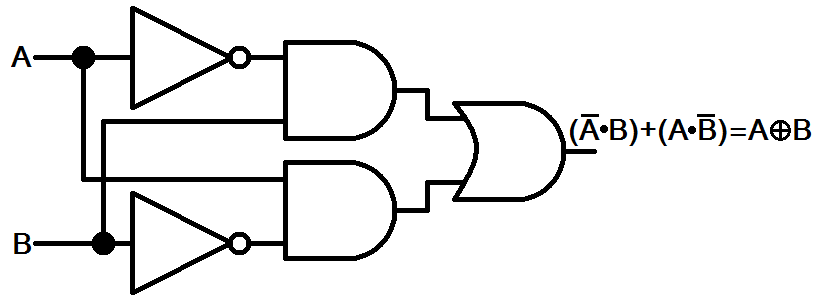
The second last logic gate in this verilog course is the xor logic gate.let's code the gate using the three modeling types: And, or, not, nand (not and), nor (not or), xor, and xnor (not xor) later building functions: If a and b are 0, the a' and b' are 1, the output is still 1. Many thanks to harry brunt, who took the time to write to me, with this interesting idea for an xnor gate (like an xor gate followed by an inverter). The logic gate performs this modulo sum operation without including carry is known as xor gate. The logic diagram consists of gates and symbols that can directly replace an expression in boolean arithmetic. As can be seen in the logic diagram below, the xor gate is built by combining three more simple gates, the or gate, the nand gate and the and gate to produce the desired result. Xor gate also known as exclusive or gate is a logic gate which produces high state '1' only when there is an odd number of high state '1' inputs. The logic low voltage is approximately. This gate is mainly used in applications where there is a need for mathematical calculations. It is an electronic circuit having one or more than one input and only one output. (euler graph and stick diagram) part i: Logic gates • digital circuit that either allows a signal to pass through it or not.
Gate level, dataflow, and behavioral modeling. In this post, you will be learned to write the programming in plc using logic gates. Only when both inputs are a logic 0 will the output be a logic 1. As can be seen in the logic diagram below, the xor gate is built by combining three more simple gates, the or gate, the nand gate and the and gate to produce the desired result. Click on the following equations to draw.
Xor Gate Circuit Diagram from circuitdigest.com Gate level, dataflow, and behavioral modeling. • aoi/oai structured logic • xor/xnor using structured logic. In this post, you will be learned to write the programming in plc using logic gates. Although not a basic logic gate in its own right, its usefulness and versatility has turned it into a standard logical function complete with its own boolean expression, operator and symbol. Mason lecture notes page 3.2 review: Xnor logic diagram you can see in the above figure if a and b are 1, then a' and b' are zero, the output is also 1. (euler graph and stick diagram) part i: B + a.b.unlike the or gate, this gate has an output is 0 when both inputs are 1.
B + a.b.unlike the or gate, this gate has an output is 0 when both inputs are 1.
(note that the caret does not denote logical conjunction (and) in these languages, despite the similarity of symbol.). A boolean expression for the xor gate can be written in two ways. Designing a xor gate looking at figure 12.18 shows that the topology of this circuit consists of two extra inverters and we have a total of 12 mosfets in this design of a xor gate. The logic gate performs this modulo sum operation without including carry is known as xor gate. It has n (n > = 2) input and one output. A logic gate is a device that can perform one or all of the boolean logic operations and, nand, nor, not, or, xnor, and xor. Xor gate sometimes eor or exor and pronounced as exclusive or is a digital logic gate that gives a true 1 or high output when the number of true inputs is odd. Logic gates a b out 0 0 0 0 1 1 1 0 1 1 1 1 a b out 0 0 0 0 1 0 1 0 0 Click on the following equations to draw. In this post, you will be learned to write the programming in plc using logic gates. Drive xor gate from nand gateusing digital logic. So in calculators, computers and many digital applications use this gate. For circuit schematic and components list visit: