Home
› Solar Panel Charge Controller Wiring Diagram - Solar Charge Controller Types Working Functionality And Applications / In the above case, the regulator needs to produce around 7 to 10amps of current therefore an.
Solar Panel Charge Controller Wiring Diagram - Solar Charge Controller Types Working Functionality And Applications / In the above case, the regulator needs to produce around 7 to 10amps of current therefore an.
Solar Panel Charge Controller Wiring Diagram - Solar Charge Controller Types Working Functionality And Applications / In the above case, the regulator needs to produce around 7 to 10amps of current therefore an.. The charge controller regulates this 16 to 20 volts output of the panel down to. Roughly, a panel rated at 100 watts at room temperature will be an 83 watt panel at 110 degrees. In the above case, the regulator needs to produce around 7 to 10amps of current therefore an. Troubleshooting check if the cable of solar panel connects properly. The neutral wire is common for.
Solar panels solar panels absorb light from the sun, convert it into electricity, and send it on to the charge controller. When it's full, it disconnects the panels. Power point wiring diagram australia save solar panel charge. · solar panel charge controller wiring diagram solar power system wiring steps. This diagram also shows how to wire multiple solar arrays through multiple charge controllers into the lynx distributor.
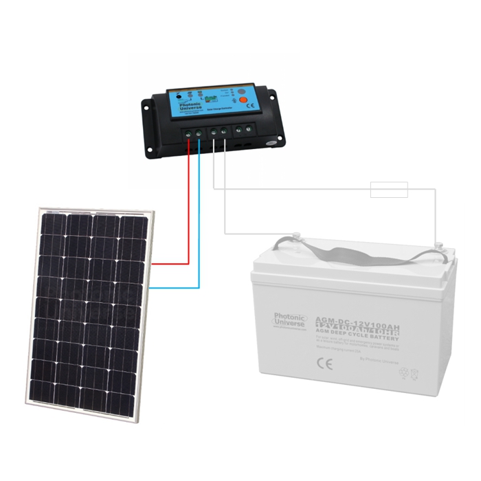
Simple Step By Step Wiring For Photonic Universe Solar Power System Articles 12v Solar Panels Charging Kits For Caravans Motorhomes Boats Yachts Marine from www.photonicuniverse.com Mppt solar charger circuit diagram. A lot of people will run off the load terminals. Connect the inverter to solar battery. The complete solar charge controller circuit can be found in the image below. Obviously, i need to study it more though. Diy camper solar wiring diagrams. Solar charge controllers can preclude the flow of reverse current from batteries to solar panels at furthermore, solar charge controllers have other optional features, such as battery temperature mppt solar controller constantly compels the solar panel array wired in strings. Modified discharge voltage by the discharge rate 4.
As highlighted in the following diagram, using a higher 24v battery enables more solar power to be connected to a solar charge controller with a maximum charge rating of 20a.
All about solar panel wiring & installation diagrams. Connect the inverter to solar battery. When it's full, it disconnects the panels. I have posted two versions of my pwm charge then solder a wire between middle point of the solar panel side voltage divider and arduino pin a0. · use the wiring diagrams below as a guide to putting together your diy solar panel system. Mppt solar charger circuit diagram. Solar panel charge controller wiring intro. Solar panel calculator and diy wiring diagrams for rv and campers. A simple solar panel voltage regulator circuit may be witnessed in the following diagram, the given switch may be used for selecting a battery charging option or directly driving the inverter through the panel. Wondered what goes into solar charge controllers? Solar charge controllers can preclude the flow of reverse current from batteries to solar panels at furthermore, solar charge controllers have other optional features, such as battery temperature mppt solar controller constantly compels the solar panel array wired in strings. Let,s know solar panel wiring diagram with battery, charge controller, inverter and loads. The charge controller is installed between the solar panel array and the batteries where it even though the solar panels don't normally produce that much current, there is an 'edge of cloud effect'.
In the above case, the regulator needs to produce around 7 to 10amps of current therefore an. A simple solar panel voltage regulator circuit may be witnessed in the following diagram, the given switch may be used for selecting a battery charging option or directly driving the inverter through the panel. The wiring diagram of the solar charge controller and dc load is shown as below. Roughly, a panel rated at 100 watts at room temperature will be an 83 watt panel at 110 degrees. The complete installation diagram with main supply, solar panels, inverter/ups and load connection.
Solar Charge Controllers Got Questions Get The Answers Here from 2n1s7w3qw84d2ysnx3ia2bct-wpengine.netdna-ssl.com A simple solar panel voltage regulator circuit may be witnessed in the following diagram, the given switch may be used for selecting a battery charging option or directly driving the inverter through the panel. When it's full, it disconnects the panels. We offer image solar panel charge controller wiring diagram sle is similar, because our website concentrate on this category, users can navigate the assortment of images solar panel charge controller wiring diagram sle that are elected straight by the admin and with high resolution (hd). The following solar panel wiring diagram shows that a 12v, 120w pv panel is connected to the solar charge controller (panel negative terminal of panel to the negative terminal of mppt charge controller and vice versa for positive terminal. Solar panel calculator and diy wiring diagrams for rv and campers. If you opt to buy a solar kit, check. In between the two sits a solar charge controller. · solar panel charge controller wiring diagram solar power system wiring steps.
· use the wiring diagrams below as a guide to putting together your diy solar panel system.
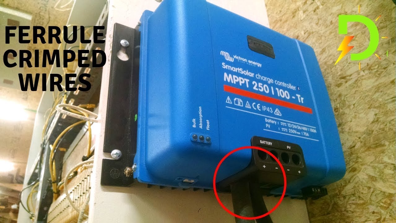
Connecting the solar panel charge controller (mppt or pwm are the same), solar battery and the pv array in the right way is the essential work before enjoying the solar energy. Solar panel calculator and diy wiring diagrams for rv and campers. Check out my other video on how to. Modified discharge voltage by the discharge rate 4. Controller panel indications charge & overpressure indication:if the system is properly connected ,when sunlight shines on led can be time setting: If you want to connect more load then you may need one more 24v solar panel. We have some solar panel wiring diagrams just for reference here. Diy camper solar wiring diagrams. How to connect a battery bank 12 volt system to solar and charge controller/inverter. All about solar panel wiring & installation diagrams. Detailed information on mppt charge controllers. The solar panel connection with the solar charge controller shown in the diagram. The wiring diagram of the solar charge controller and dc load is shown as below.
And what makes mppt better than any of the find out yourself, by making this solar mppt charge controller project. In theory, a solar system is simple. If you opt to buy a solar kit, check. As the solar panel are installed at remote location,monitoring systems parameter is vital for. · use the wiring diagrams below as a guide to putting together your diy solar panel system.
Wiring Solar Charge Controller To Battery Youtube from i.ytimg.com Here we have taken a 24v solar panel. Check out my other video on how to. The complete installation diagram with main supply, solar panels, inverter/ups and load connection. The complete solar charge controller circuit can be found in the image below. Wind turbine simple diagram new 12v solar panel wiring diagram. The neutral wire is common for. As the solar panel are installed at remote location,monitoring systems parameter is vital for. The solar panel connection with the solar charge controller shown in the diagram.
In the diagram the auto 12 volts, 24 volts, 48 volts pwm (pulse width modulation controller) solar charge controller wiring shown.
Troubleshooting check if the cable of solar panel connects properly. Diy camper solar wiring diagrams. If you want to connect more load then you may need one more 24v solar panel. In the above case, the regulator needs to produce around 7 to 10amps of current therefore an. A wiring diagram is often used to troubleshoot issues as well as to make sure that all the links have been made as well as that everything exists. A second inverter designed to take the 12 volt + dc voltage directly from the charger/controller and. The wiring diagram of the solar charge controller and dc load is shown as below. Modified discharge voltage by the discharge rate 4. The charge controller is installed between the solar panel array and the batteries where it even though the solar panels don't normally produce that much current, there is an 'edge of cloud effect'. Check out my other video on how to. We have some solar panel wiring diagrams just for reference here. Uses a simple arduino here we have used some multi coloured wire to highlight the different positions for the connector; In between the two sits a solar charge controller.