Home
› Furnace Control Wiring : Furnace Thermostat Wiring And Troubleshooting Hvac How To / It is a red wire and comes from the transformer usually located in the air handler for split systems, but you may find the transformer in the condensing unit.
Furnace Control Wiring : Furnace Thermostat Wiring And Troubleshooting Hvac How To / It is a red wire and comes from the transformer usually located in the air handler for split systems, but you may find the transformer in the condensing unit.
Furnace Control Wiring : Furnace Thermostat Wiring And Troubleshooting Hvac How To / It is a red wire and comes from the transformer usually located in the air handler for split systems, but you may find the transformer in the condensing unit.. Connect the yellow wire from the venstar device to the y terminal on the hvac control board. This diagram is to be used as reference for the low voltage control wiring of your heating and ac system. Note that the control board is often found in the blower cabinet and you're going to have to defeat a safety switch to perform testing there. Test the power coming into your control board. With such an illustrative guidebook, you'll have the ability to troubleshoot, stop, and full your projects easily.
Standard ac with standard furnace control wiring standard furnace standard thermostat standard a/c condenser 1st stage heat (white) 24 volt+ fan only operation common air conditioning ac contactor control board 1 this diagram is to be used as reference for the low voltage control wiring of your heating and ac system. Or vendor supplied wires may not be color coded as noted in the chart above. With such an illustrative guidebook, you'll have the ability to troubleshoot, stop, and full your projects easily. Put the access panel back on the furnace. Type the full model number of your furnace into our website's search bar to find all the parts that will perfectly fit your particular model, from igniters and flame sensors, to blower wheels, control boards, wire harnesses, and terminal blocks.
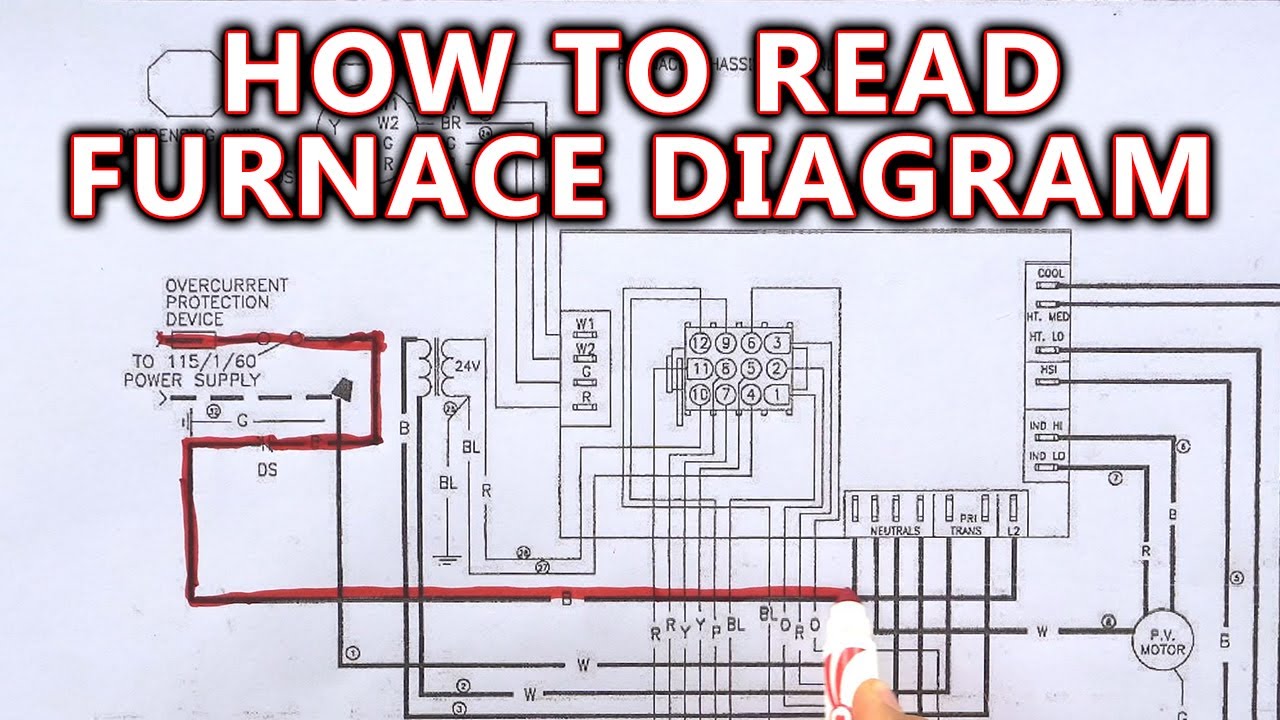
How To Read Furnace Wiring Diagram Youtube from i.ytimg.com It terminates at your air handler or furnace. Suburban furnace control module board wiring kit 520832. If both led lights are off, there might be a problem with the furnace wiring, supplied voltage, circuit breaker, transformer, control board or door lock. It shows the components of the circuit as simplified shapes, and the power as well as signal connections between the devices. Goodman time delay circuit board pcbfm103 b1370735s shortys pumps located near indianapolis indiananationwide armstrong pump distributor. Click on the image to enlarge, and then save it to your computer by right clicking on the image. Wiring notes for the combination furnace control l4064b. Connect the yellow wire from the venstar device to the y terminal on the hvac control board.
With such an illustrative guidebook, you'll have the ability to troubleshoot, stop, and full your projects easily.
Furnace control board wiring page 1 line 17qq com. In many wiring diagrams, you'll see notations saying something like, if any of the original wire supplied with this unit must be replaced, it must be replaced with type 105c thermoplastic or its equivalent. if you don't know what you are looking for, trying to find. Notesome ac systems will have a blue wire with a pink stripe in place of the yellow or y wire. Connect the yellow wire from the venstar device to the y terminal on the hvac control board. Thanks for watching!!!please consider clicking below to help support our ch. Click on the image to enlarge, and then save it to your computer by right clicking on the image. The (w) white wire is not available on cool only thermostats. Applicable to models (links in blue): This control can be wired to serve as a safety limit switch on a furnace by wiring just the limit terminals on the control. Test the power coming into your control board. Furnace low voltage wiring diagram. Typically, the yellow wire will be run to the air handler where at the air handler, this wire is usually connected to another wire (typically by a wire nut. Wiring notes for the combination furnace control l4064b.
Wiring notes for the combination furnace control l4064b. Goodman time delay circuit board pcbfm103 b1370735s shortys pumps located near indianapolis indiananationwide armstrong pump distributor. A wiring diagram is a type of schematic which makes use of abstract pictorial symbols to reveal all the interconnections of parts in a system. It is a red wire and comes from the transformer usually located in the air handler for split systems, but you may find the transformer in the condensing unit. In this video i show where all the wires go on this bryant furnace control board.
What Is A C Wire And Why S It So Important For Your Smart Thermostat from thesmartcave.com This can be tested right at the furnace control board too, avoiding all doubt about the thermostat wiring. Armstrong air wiring diagrams page 2 line 17qq com. Applicable to models (links in blue): Notesome ac systems will have a blue wire with a pink stripe in place of the yellow or y wire. If the wire is not already connected to the furnace, connect it to the proper terminal according to your furnace owner's manual. With such an illustrative guidebook, you'll have the ability to troubleshoot, stop, and full your projects easily. Furthermore, it will be one of the few control wires (thermostat wires) that will terminate at the condenser in a split system air conditioner and heating system. Next, locate the line voltage by locating the wire that runs from the door switch to the control board.
Connect the green wire from the venstar device to the g terminal on the hvac control board.
A wiring diagram is a streamlined conventional pictorial representation of an electrical circuit. If both led lights are off, there might be a problem with the furnace wiring, supplied voltage, circuit breaker, transformer, control board or door lock. No power to control or board fault detected. Armstrong air wiring diagrams page 2 line 17qq com. It shows the components of the circuit as simplified shapes, and the power as well as signal connections between the devices. It terminates at your air handler or furnace. This is the wire bringing 120 volts to your furnace. Turn the power for the furnace and thermostat back on at the circuit breaker. Always refer to your thermostat or equipment installation guides to verify proper wiring. Thanks for watching!!!please consider clicking below to help support our ch. In many wiring diagrams, you'll see notations saying something like, if any of the original wire supplied with this unit must be replaced, it must be replaced with type 105c thermoplastic or its equivalent. if you don't know what you are looking for, trying to find. Click on the image to enlarge, and then save it to your computer by right clicking on the image. Typically, the yellow wire will be run to the air handler where at the air handler, this wire is usually connected to another wire (typically by a wire nut.
No power to control or board fault detected. Control wire from the thermostat furnace note: The (w) white wire is not available on cool only thermostats. With such an illustrative guidebook, you'll have the ability to troubleshoot, stop, and full your projects easily. Furnace wiring must be rated to safely take the heat of a furnace.
Use External Switch To Control Blower Fan On Furnace Home Improvement Stack Exchange from i.stack.imgur.com Type the full model number of your furnace into our website's search bar to find all the parts that will perfectly fit your particular model, from igniters and flame sensors, to blower wheels, control boards, wire harnesses, and terminal blocks. Assortment of beckett oil furnace wiring diagram. Armstrong air wiring diagrams page 2 line 17qq com. The 18 refers to the gauge and the 5 refers to how many individual wires are inside the cable. This control can be wired to serve as a safety limit switch on a furnace by wiring just the limit terminals on the control. In this video i show where all the wires go on this bryant furnace control board. It shows the components of the circuit as simplified shapes, and the power as well as signal connections between the devices. Click on the image to enlarge, and then save it to your computer by right clicking on the image.
If the wire is not already connected to the furnace, connect it to the proper terminal according to your furnace owner's manual.
How to wire the fan & limit control wire and test the combination fan and limit control on a furnace. Always refer to your thermostat or equipment installation guides to verify proper wiring. Wiring notes for the combination furnace control l4064b. Furnace low voltage wiring diagram. Click on the image to enlarge, and then save it to your computer by right clicking on the image. Standard ac with standard furnace control wiring standard furnace standard thermostat standard a/c condenser 1st stage heat (white) 24 volt+ fan only operation common air conditioning ac contactor control board 1 this diagram is to be used as reference for the low voltage control wiring of your heating and ac system. Suburban furnace control module board wiring kit 520832. Most furnaces have a power switch in the central control or the heating system. With such an illustrative guidebook, you'll have the ability to troubleshoot, stop, and full your projects easily. Notesome ac systems will have a blue wire with a pink stripe in place of the yellow or y wire. Assortment of beckett oil furnace wiring diagram. Aprilaire 500m wiring to furnace control board first off, i think this website is great and i have read lots of tips over the l. Control wire from the thermostat furnace note: