Home
› Solar Panels Circuit Diagram : Energy Saving: Diy 12v solar panel - Rather than connecting the positive terminal of one panel to the negative terminal of the next, when stringing in parallel, the positive terminals of all the panels on the string are connected to one wire and the negative terminals are all connected to another wire.
Solar Panels Circuit Diagram : Energy Saving: Diy 12v solar panel - Rather than connecting the positive terminal of one panel to the negative terminal of the next, when stringing in parallel, the positive terminals of all the panels on the string are connected to one wire and the negative terminals are all connected to another wire.
Solar Panels Circuit Diagram : Energy Saving: Diy 12v solar panel - Rather than connecting the positive terminal of one panel to the negative terminal of the next, when stringing in parallel, the positive terminals of all the panels on the string are connected to one wire and the negative terminals are all connected to another wire.. When autocomplete results are available use up and down arrows to review and enter to select. When battery voltage extends to 13.8v, the relay contacts click, so that 2n3055 transistor begins trickle charging the battery to a optimum of. Keep in mind that the number of solar panels and batteries depends on the load requirements where solar panels keep charging the batteries as well as power up the ac load. So, if you wired the same panels from before in parallel, the voltage of the system would remain at 40 volts, but the amperage would increase to 10 amps. He needs batteres to supply the 1500w loads for 12hours at night.
Solar energy is simply the light and heat that come from the sun people can harness the sun energy in a few different ways photovoltaic cells which convert s. This is a good amount of power. These diagrams are designed to be understood by a beginner for a safe and effective install with readily accessible components. Solar energy systems wiring diagram examples: Connect the positive terminal of the first solar panel to the negative terminal of the next one.
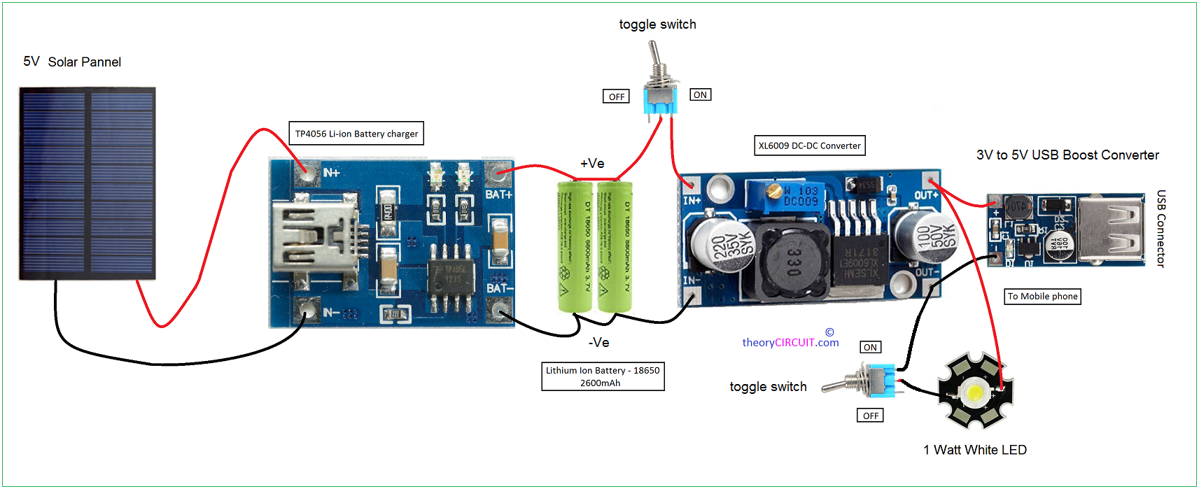
Solar Power Bank Circuit from theorycircuit.com I'm posting this for the beginner. These diagrams are designed to be understood by a beginner for a safe and effective install with readily accessible components. Power wire wind power diy solar alternative energie advantages of solar energy solar roof solar projects energy projects best solar panels. Saved by bookingritzcarlton wiring diagram database. It reveals the elements of the circuit as streamlined shapes, and the power and also signal links between the gadgets. When autocomplete results are available use up and down arrows to review and enter to select. Stringing solar panels in parallel (shown in the diagram above) is a bit more complicated. Search for solar panels homes.
So, if you wired the same panels from before in parallel, the voltage of the system would remain at 40 volts, but the amperage would increase to 10 amps.
I'm posting this for the beginner. Use the wiring diagrams below as a guide to putting together your diy solar panel system. He needs batteres to supply the 1500w loads for 12hours at night. Wiring solar panels in parallel causes the amperage to increase, but the voltage remains the same. Let's look at a numerical example. To understand well how to construct a solar inverter, it is vital to study how the circuit operates through with the help of following steps: A wiring diagram is a type of schematic which makes use of abstract pictorial icons to reveal all the affiliations of elements in a system. Here, energy from the solar panel is supplied to the battery via a relay and rectifier diode. A voluntary solar power supply circuit and a transformer may be added within to charge the battery when necessary (check diagram). Wiring solar panels in a parallel circuit Solar energy is simply the light and heat that come from the sun people can harness the sun energy in a few different ways photovoltaic cells which convert s. 2 kilowatts, 4 kilowatts, and 8 kilowatts. Between the two is a reverse blocking diode.
This circuit is a little different than the circuits that use the solar cell for a dark detection; Circuitry diagrams are made up of two points: Search for solar panels homes. Both the above flaws are effectively removed in this simple solar regulator circuit. It reveals the elements of the circuit as streamlined shapes, and the power and also signal links between the gadgets.
Energy Saving: Diy 12v solar panel from 2.bp.blogspot.com A wiring diagram is a streamlined conventional photographic depiction of an electric circuit. There are a few different ways to arrange panels, batteries, and connectors. To understand well how to construct a solar inverter, it is vital to study how the circuit operates through with the help of following steps: Now the diode is placed right after the solar cell so q1 and q2 are powered by the battery. Wiring solar panels in parallel causes the amperage to increase, but the voltage remains the same. When autocomplete results are available use up and down arrows to review and enter to select. Saved by bookingritzcarlton wiring diagram database. 2 kilowatts, 4 kilowatts, and 8 kilowatts.
When battery voltage extends to 13.8v, the relay contacts click, so that 2n3055 transistor begins trickle charging the battery to a optimum of.
We have also procured 800 solar light kits from a manufacturer, which the children will assemble, however, we need someone to simplify the circuit diagram of these light kits, which will be used for simple lessons on electricity, circuits, and calculation of power, volts, current and conversion of solar energy to electrical energy. Let's look at a numerical example. Use the wiring diagrams below as a guide to putting together your diy solar panel system. Image of wiring diagram of solar panel system example circuit diagrams of solar energy systems. Solar concept is not new for us. There are a few different ways to arrange panels, batteries, and connectors. I'm posting this for the beginner. This diagram also shows how to wire multiple solar arrays through multiple charge controllers into the lynx distributor. Icons that represent the parts in the circuit, as well as lines that stand for the links in between. Dc to ac inverter for ac power. Here, energy from the solar panel is supplied to the battery via a relay and rectifier diode. Touch device users, explore by touch or with swipe gestures. Connect the positive terminal of the first solar panel to the negative terminal of the next one.
Rather than connecting the positive terminal of one panel to the negative terminal of the next, when stringing in parallel, the positive terminals of all the panels on the string are connected to one wire and the negative terminals are all connected to another wire. It reveals the elements of the circuit as streamlined shapes, and the power and also signal links between the gadgets. Dividing by 50% depth of discharge as you choose flooded, that is 18000/0.5=36000wh or divde by 0.8 if for agm batteries, that is 18000/0.8 = 22500wh. When autocomplete results are available use up and down arrows to review and enter to select. 1 shows the circuit of the solar tracking system.
Wiring Diagram: Solar Install 100w Panel with MPPT Controller with Battery Monitor | Off-Grid Camper from www.offgridcamper.co.uk Assortment of wiring diagram for solar panel to battery. Power wire wind power diy solar alternative energie advantages of solar energy solar roof solar projects energy projects best solar panels. Say you have 2 x 100 watt solar panels and a 24v battery bank. Find out how much you can save with home solar with the click of a button. Dividing by 50% depth of discharge as you choose flooded, that is 18000/0.5=36000wh or divde by 0.8 if for agm batteries, that is 18000/0.8 = 22500wh. Just click the link to go straight to the wiring diagram for the size closest to your chosen system. Between the two is a reverse blocking diode. Stringing solar panels in parallel (shown in the diagram above) is a bit more complicated.
Solar tracking system circuit fig.
Use the wiring diagrams below as a guide to putting together your diy solar panel system. Search for solar panels homes. Find out how much you can save with home solar with the click of a button. I'm posting this for the beginner. It reveals the elements of the circuit as streamlined shapes, and the power and also signal links between the gadgets. When autocomplete results are available use up and down arrows to review and enter to select. A wiring diagram is a type of schematic which makes use of abstract pictorial icons to reveal all the affiliations of elements in a system. This circuit uses a photo resistor for the dark sensor in place of the solar cell. There are a few different ways to arrange panels, batteries, and connectors. Image of wiring diagram of solar panel system example circuit diagrams of solar energy systems. Keep in mind that the number of solar panels and batteries depends on the load requirements where solar panels keep charging the batteries as well as power up the ac load. Circuit of solar tracking system. A wiring diagram is a simplified conventional pictorial depiction of an electric circuit.