Charger Pcb Diagram : Earbud Charger Pcb Circuit Schematic Page 2 Line 17qq Com : Not using ics and complicated devices.. The output current chart is also mentioned. Mobile phones generally charge with 5v regulated dc supply, so basically we are going to build a circuit diagram for 5v regulated dc supply from 220 ac. This is the very simple automatic 12v portable car battery charger circuit diagram. Instead keep a 1000uf/25v capacitor connected right across the relay coil. The circuit is nothing but a 12v dc power supply with an ammeter for monitoring the charging current.
Nowadays mobiles can also be charged using the usb outlet of pc. In the circuit has two led indicators. This battery charger circuit provides the automatic cut off the facility when the battery gets fully charged. Steps for making the automatic battery charger circuit on pcb. This circuit can also be used as power supply for other devices, breadboards, microcontrollers and ics.
Battery Charger Work In Progress Pcb Modding For Constant Current Source Electronics from i.redd.it The ic 555 is so versatile, it can be considered the single chip solution for all circuit application needs. At the absorption stage, the remaining 20% of the battery is charged. May 2, 2012 by ashutosh bhatt. Just have to understand battery charging requirements only. The following image shows the circuit diagram of one such implementation. Actual size solder side and component side pcb design is shown below. Simple 12v battery charger with battery indicator. Car battery charger circuit 12 volt simple 12v circuits using make a gel cell max 20 rms 1 3ah automatic automotive 7ah smart with pcb lead acid full diy gelled electrolyte regulated auto cut off 100ah voltage float diagram for best portable arduino 24v 12vdc mobile power tricky guardian layout v overcharge electronic page diagrams solar alkaline universal charging lm7815
Solder those components as shown in the circuit.
This circuit can be used to charge all type of 12v rechargeable batteries including car batteries. You can charge multiple voltage batteries with the help of the input voltage chart given below for example if you want to charge 1.2v battery then the minimum voltage should be 6.5v and maximum should be 10v. The mobile charger circuit presented in this project can give 4.7v of synchronized voltage for charging the phone. How to build a, 12v automotive battery charger using a ic tca 965 At the absorption stage, the remaining 20% of the battery is charged. And the mobile charger is an electronics device that is used to charge a mobile phone battery. Circuit diagram of tp4056 lithium ion battery charger. Steps for making the automatic battery charger circuit on pcb. Components of lead acid battery charger circuit. May 2, 2012 by ashutosh bhatt. A portable mobile charger means a small size mobile charger, which you can carry every ware. Before the use of this circuit, you need to adjust the cut off voltage range for the auto cut. Instead keep a 1000uf/25v capacitor connected right across the relay coil.
The components needed are as follows: Portable mobile charger circuit diagram. This dc supply can be used to charge mobiles as well as the power source for digital circuits, breadboard circuits, ics, microcontrollers etc. The circuit diagram of the lead acid battery charger is given below. Pcb layout for battery charger circuit with lm317.
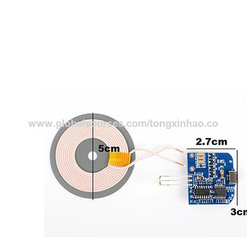
China Multifunctional Power Bank Pcb Board Pcba Supplier And Charger Pcb Circuit Board Pcba Made In China On Global Sources Pcb Multilayer Flexible Pcbs Multilayer Pcb from p.globalsources.com Instead keep a 1000uf/25v capacitor connected right across the relay coil. Three of its opamps have been employed here. No doubt it's been utilized here too for yet another useful application. See more ideas about battery charger circuit, circuit, circuit diagram. Nowadays mobiles can also be charged using the usb outlet of pc. This is the very simple automatic 12v portable car battery charger circuit diagram. Simple automatic battery charger circuit. The following image shows the circuit diagram of one such implementation.
This is the very simple automatic 12v portable car battery charger circuit diagram.
Portable mobile charger circuit diagram. But even though, you can get a clear overview of the mobile charger circuit from the above diagram. The diode d1 is a 1n4148 which effectively acts as the temperature sensor here. This is the first automatic battery charger circuit. The following image shows the circuit diagram of one such implementation. As usb outlets can give 5v dc and 100ma of current. Here is the circuit diagram of a simple and straight forward 12 v battery charger circuit with diagram. The project is the nimh battery charger circuit with automatic cutoff when fully charged. Three of its opamps have been employed here. Print the pcb layout and stick it on acrylic sheet or cardboard. Please do not use a filter capacitor across the bridge. Simple automatic battery charger circuit. Just have to understand battery charging requirements only.
The first circuit diagram below shows a precise temperature sensor circuit using the ic lm324. Use existing products to use more benefits. Connect all the components as shown on the layout. The project is the nimh battery charger circuit with automatic cutoff when fully charged. First led, show charging status, when the battery is full, it will be off.
Mobile Phone Parts Identification How To Identify Parts Components from i0.wp.com The project is the nimh battery charger circuit with automatic cutoff when fully charged. No doubt it's been utilized here too for yet another useful application. Before the use of this circuit, you need to adjust the cut off voltage range for the auto cut. Please do not use a filter capacitor across the bridge. But even though, you can get a clear overview of the mobile charger circuit from the above diagram. You can charge multiple voltage batteries with the help of the input voltage chart given below for example if you want to charge 1.2v battery then the minimum voltage should be 6.5v and maximum should be 10v. If the terminal voltage of the battery reduces below the set level, say 13.5 volts, the circuit automatically turns on to the charge mode. Car battery charger circuit 12 volt simple 12v circuits using make a gel cell max 20 rms 1 3ah automatic automotive 7ah smart with pcb lead acid full diy gelled electrolyte regulated auto cut off 100ah voltage float diagram for best portable arduino 24v 12vdc mobile power tricky guardian layout v overcharge electronic page diagrams solar alkaline universal charging lm7815
Not using ics and complicated devices.
The circuit is nothing but a 12v dc power supply with an ammeter for monitoring the charging current. This is a simple 12v battery charger circuit with indicator circuit is a smart charger circuit. Part list of the mobile charger circuit We use the concept of the circuit: The project is the nimh battery charger circuit with automatic cutoff when fully charged. Nowadays mobiles can also be charged using the usb outlet of pc. But even though, you can get a clear overview of the mobile charger circuit from the above diagram. Three of its opamps have been employed here. In this project we will be making a circuit that will be used to get 5 volts regulated dc supply from 220 volts of ac supply. It is sufficient for slow charging of mobile. Use existing products to use more benefits. The design is quite straight forward, built on a paper phenolic pcb, could be easily repaired. We can use this circuit for all battery.