Home
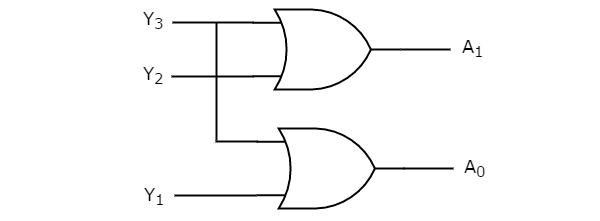
› Encoder Logic Diagram And Truth Table : Team Bostonu Encoder 2014 Igem Org - The encoder can, therefore, be implemented with or gates whose inputs are determined directly from the truth table as shown in the image below
Encoder Logic Diagram And Truth Table : Team Bostonu Encoder 2014 Igem Org - The encoder can, therefore, be implemented with or gates whose inputs are determined directly from the truth table as shown in the image below
Encoder Logic Diagram And Truth Table : Team Bostonu Encoder 2014 Igem Org - The encoder can, therefore, be implemented with or gates whose inputs are determined directly from the truth table as shown in the image below. When a logic gate has only two inputs, or the logic circuit to be analyzed has only one or two gates, it is fairly easy to remember how a. The truth tables of logic gates are very complex but larger than the not gate. Encoder boolean function (simplified form). Logic diagram of 2:4 decoder. The circuit diagram of 4 to 2 priority encoder is shown in the following figure.
See the best & latest encoder truth table on iscoupon.com. The truth table consists of four rows , since , it is assumed that only one input is the value of 1 then the corresponding binary code associated with that enabled input is displayed at the outputs. Why we use encoder 3. Truth tables offer a simple and easy to understand tool that can be used to determine the output of any logic gate or circuit for all input combinations. The user inputs the output values in the x column it will be a chart much like this
Priority Encoder Laptrinhx from www.electronicshub.org Encoder a block diagram b logical truth table c schematic. The truth table consists of four rows , since , it is assumed that only one input is the value of 1 then the corresponding binary code associated with that enabled input is displayed at the outputs. Encoder boolean function (simplified form). You can enter logical operators in several different formats. Truth table of an 8:3 encoder. From this truth table, the boolean expression for the encoder above with data inputs d0 to d7 and outputs q0, q1, q2 is given as Every boolean expression can be viewed as a truth table. The logical expression of the term a0 and a1 is as follows:
The circuit diagram of 4 to 2 priority encoder is shown in the following figure.
Encoders are combinational logic circuits and they are exactly opposite of decoders. An encoder is a combinational logic circuit that can be used to convert 2^n lines of digital input into n bits of coded binary output. Hello everyone, today we are going to know about the topics listed below… 1. ● for each row in the truth table, for the function, where the output is 1, set the corresponding data input of the multiplexer to 1. It is used to find out if a propositional expression is true for all legitimate input values. Logical circuit of the above expressions is given below: The truth table of octal to binary encoder is shown below. Flip flops input equations and the circuit output are as follows; An encoder is a circuit that changes a set of signals into a code. Different types of encoder 4. What is a priority encoder? Decoder, 3 to 8 decoder block diagram, truth table, and. As you can see the logical diagram of the 8×3 lines encoder is very simple.
This indicates the off state of the decoder which can also be considered to be its reset state. A = 0, b = 1, c = 1. As you can see the logical diagram of the 8×3 lines encoder is very simple. Once we obtain the boolean expression we just have to draw it in form of gates. From the truth table, the outputs can be expressed by following boolean function.
The Quantum Bcd Priority Encoder Book Chapter Iopscience from cdn.iopscience.com Encoders are combinational logic circuits and they are exactly opposite of decoders. A = 0, b = 1, c = 1. Thus one has to drive high on the enable. Logic circuits are designed to perform a particular function, understanding the nature of that function requires a logic circuit truth table. Does my truth table correct? Decoder, 3 to 8 decoder block diagram, truth table, and. This indicates the off state of the decoder which can also be considered to be its reset state. Logical expression for a1 and a0
The truth table of 4 to 2 encoder is as follows :
A = 0, b = 1, c = 1. A logic diagram uses the pictoral description of logic gates in combination to represent a logic expression. Encoder boolean function (simplified form). The user inputs the output values in the x column it will be a chart much like this A sequential circuit has two d flip flops a and b, two inputs x and y and one output z. The encoder can, therefore, be implemented with or gates whose inputs are determined directly from the truth table as shown in the image below Flip flops input equations and the circuit output are as follows; Different types of encoder 4. 8 to 3 line encoder: A general encoder's block diagram. Da = x'y' + y'a db = y'b + xa z = b' (i) draw the logic diagram of the table. The block diagram and truth table of a 4 input encoder is shown in below figure. Logic gates and truth tables.
As you can see the logical diagram of the 8×3 lines encoder is very simple. A logic diagram uses the pictoral description of logic gates in combination to represent a logic expression. An encoder is a circuit that changes a set of signals into a code. Once we obtain the boolean expression we just have to draw it in form of gates. The block diagram and truth table of a 4 input encoder is shown in below figure.
Digital Circuits Encoders Tutorialspoint from www.tutorialspoint.com This tool generates truth tables for propositional logic formulas. Encoder in digital logic geeksforgeeks. We will discuss each herein and demonstrate ways to convert between them. As you can see the logical diagram of the 8×3 lines encoder is very simple. From this truth table, the boolean expression for the encoder above with data inputs d0 to d7 and outputs q0, q1, q2 is given as Where x equals dont care, that is it can be at a logic 0 level or at a logic 1 level. We can implement the above boolean functions using logic gates. Once we obtain the boolean expression we just have to draw it in form of gates.
The encoders and decoders are designed with logic gates such as and gate.
The encoders and decoders are designed with logic gates such as and gate. The 8 to 3 line encoder is also known as octal to binary encoder. From the truth table, the outputs can be expressed by following boolean function. All of coupon codes are verified and tested today! Encoder in digital logic geeksforgeeks. Every boolean expression can be viewed as a truth table. When logic gates are connected they form a circuit. The figure below shows the logic symbol of 4 to 2 encoder : The block diagram and truth table of a 4 input encoder is shown in below figure. Find 4:2 encoder, 8:3 encoder and 4:2 priority encoder circuit, truth table and boolean building encoders using combinational logic designs. It is therefore possible to move between boolean logic expressions and truth tables. A = 0, b = 1, c = 1. What is a priority encoder?