Home
› Bass Treble Circuit Diagram / Simple Audio Tone Control Circuit / Following are the circuit diagram of amplifier, bass treble used in all amplifier projects.
Bass Treble Circuit Diagram / Simple Audio Tone Control Circuit / Following are the circuit diagram of amplifier, bass treble used in all amplifier projects.
Bass Treble Circuit Diagram / Simple Audio Tone Control Circuit / Following are the circuit diagram of amplifier, bass treble used in all amplifier projects.. In the figure below, we have presented the circuit diagram of one channel only for clarity and also because the other channel has identical circuit arrangement. Following are the circuit diagram of amplifier, bass treble used in all amplifier projects. Here are some ideas for using them in the classroom: Bass treble control circuit tca730 tca730a bass treble circuit diagram bass control in stereo amplifier tca740a bass treble circuit a740a tca740 text: In the next stage, ic1b is the actual active filter that has three pass filters connected across the negative feedback loop.
8 tone control circuit, stereo preamplifier using normal transistors. See the schematic diagram below : For this circuit, you must use a dpdt on/on/on type of switch. The 0.01 cap is for high frequency while the 0.22uf cap is for low frequency. Stereo baxandall bass and treble control.
Bass Treeble Booster Circuit Electronic Circuit from 2.bp.blogspot.com Following are the circuit diagram of amplifier, bass treble used in all amplifier projects. Fender's tbx tone control, which stands for treble bass expander. The resources below aim to help children learn about the different notes on the treble clef and bass clef. 8 tone control circuit, stereo preamplifier using normal transistors. To control bass and treble effects audio low noise. The explained bass treble tone controller circuit not only facilitates the control of the bass, treble frequencies but also the mid range frequencies. But this circuit worth the try to complete your audio device at home. Here are some ideas for using them in the classroom:
The 0.01 cap is for high frequency while the 0.22uf cap is for low frequency.
The explained bass treble tone controller circuit not only facilitates the control of the bass, treble frequencies but also the mid range frequencies. Yeah i looked back at the wiring diagram i found on the internet and realized i had the hot frm he pickup selector going to the wrong place. All the headings are clickable to watch the related videos. Here is the circuit diagram of a passive dx bass circuit that can be used with almost all audio amplifiers. Following are the circuit diagram of amplifier, bass treble used in all amplifier projects. Values on the circuit diagram are subject to changes. The apparent simplicity of the circuit and the limited supply of this discontinued effect make it a perfect target for builder and guitar pedal enthusiasts. Let children use the blank posters and challenge them to add the correct. The dallas rangemaster treble booster is a booster guitar pedal that especially emphasizes the upper mid and treble frequencies (coloring the signal). The tone amplifier circuit i have often referred to the tone booster. We will begin with a high gain, high fidelity bass treble controller circuit which forms the first stage of this compact table amplifier design. Wiring diagram courtesy of seymour duncan (seymourduncan.com). The bass control is nothing but a low pass electronic circuit which filters and allows only the.
The explained bass treble tone controller circuit not only facilitates the control of the bass, treble frequencies but also the mid range frequencies. In the next stage, ic1b is the actual active filter that has three pass filters connected across the negative feedback loop. Let children use the blank posters and challenge them to add the correct. In recent columns we've been exploring passive tone systems—how they the circuit has a somewhat similar ancestor: Below is the list of circuit diagrams of mono and stereo amplifiers, bass and treble used in all amplifier project videos of this website.
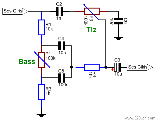
Simple Tone Control Circuit Rc Filter Bass Treble Adjustment Electronics Projects Circuits from 320volt.com This kit comes complete with all input / output connections and. The resources below aim to help children learn about the different notes on the treble clef and bass clef. The first stage acts as a main tone stage. Easy to builds with pcb. The discussed bass, treble tone controller circuit thus effectively performs like a 3 band graphic equalizer circuit allowing the user with distinct 3 way. Following are the circuit diagram of amplifier, bass treble used in all amplifier projects. This circuit can be made without even a veroboard. The complete bass treble circuit diagram is shown in the image below.
Connect all components according to circuit diagram as shown in picture.
Wiring diagram courtesy of seymour duncan (seymourduncan.com). Bass treble control circuit tca730 tca730a bass treble circuit diagram bass control in stereo amplifier tca740a bass treble circuit a740a tca740 text: The explained bass treble tone controller circuit not only facilitates the control of the bass, treble frequencies but also the mid range frequencies. Connect the output of the tone control circuit above to the input of your amplifier circuit. In the next stage, ic1b is the actual active filter that has three pass filters connected across the negative feedback loop. Nothing to say about it, as it is so simple that a beginner level hobbyist can even understand. For the values of cb and ct of 0.39 µf and 0.01 µf as shown in the application circuit, 15 db of boost or cut is obtained at 40 hz and 16 khz. The bass control is nothing but a low pass electronic circuit which filters and allows only the. This kit comes complete with all input / output connections and. The apparent simplicity of the circuit and the limited supply of this discontinued effect make it a perfect target for builder and guitar pedal enthusiasts. Bass and treble circuit is ready so now we have to connect volume potentiometer. The lm1036 is a dc controlled tone (bass/treble), volume and balance circuit for stereo applications in car radio, tv and audio systems. The passive tbx is installed on the duff.
The first stage acts as a main tone stage. Let children use the blank posters and challenge them to add the correct. Here is the circuit diagram of a passive dx bass circuit that can be used with almost all audio amplifiers. The tone amplifier circuit i have often referred to the tone booster. But this circuit worth the try to complete your audio device at home.
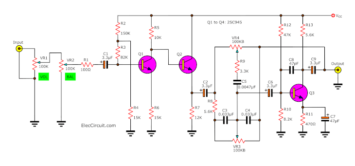
Simple Bass Treble Tone Control Circuit Diagram Eleccircuit Com from www.eleccircuit.com The apparent simplicity of the circuit and the limited supply of this discontinued effect make it a perfect target for builder and guitar pedal enthusiasts. The passive tbx is installed on the duff. Tone controller / bass and treble controller. This circuit is under:, circuits, bass and treble tone control circuit l24456 the lm1036 is a dc controlled accent (bass/treble), aggregate and antithesis ambit for stereo applications in car radio, tv and audio systems. This type of circuit that provides bass and treble control is also known as a bt circuit board. Stereo baxandall bass and treble control. Here are some ideas for using them in the classroom: Following are the circuit diagram of amplifier, bass treble used in all amplifier projects.
Fender's tbx tone control, which stands for treble bass expander.
An added ascendancy ascribe allows loudness advantage to. Its function is to strengthen the bass and treble tone gain for the audio devices you have at home. See the schematic diagram below : Mid frequency, bass and treble control circuit: The 0.01 cap is for high frequency while the 0.22uf cap is for low frequency. To control bass and treble effects audio low noise. Bass treble control circuit tca730 tca730a bass treble circuit diagram bass control in stereo amplifier tca740a bass treble circuit a740a tca740 text: And since equalizer circuit is used with audio amplifier, so there no extra power supply will required for this equalizer. Connect all components according to circuit diagram as shown in picture. Yeah i looked back at the wiring diagram i found on the internet and realized i had the hot frm he pickup selector going to the wrong place. The apparent simplicity of the circuit and the limited supply of this discontinued effect make it a perfect target for builder and guitar pedal enthusiasts. In today's video, diy heavy treble bass circuit without pcb circuit board uses two transistors 2sc1815 ➤ you can adjust the signal. The dallas rangemaster treble booster is a booster guitar pedal that especially emphasizes the upper mid and treble frequencies (coloring the signal).