Home
› Circuit Breaker Symbol Single Line Diagram : How To Read A Single Line Diagram Power Solutions Eeco : Hope you liked this circuit breaker project and understood the working behind it.
Circuit Breaker Symbol Single Line Diagram : How To Read A Single Line Diagram Power Solutions Eeco : Hope you liked this circuit breaker project and understood the working behind it.
Circuit Breaker Symbol Single Line Diagram : How To Read A Single Line Diagram Power Solutions Eeco : Hope you liked this circuit breaker project and understood the working behind it.. Simbol of eletric daigram no and nc. Only qualified persons should review schematic diagrams and perform work on circuit breakers. When interpreting a single line diagram, you should always start at the top where the highest voltage is and. Future removable or drawout circuit breaker position. A single cell or other power source is represented by a long and a short parallel a straight line is used to represent a connecting wire between any two components of the circuit.
A schematic diagram is a drawing that shows electrical system circuitry with symbols that depict electrical devices and lines representing conductors. Engineering symbology, prints and drawings, module 3. This symbol represents a single pole circuit breaker. Single line diagram of power system ~ your electrical home. All symbols > electrical installations > switchgear and protective devices (ansi) > protective devices > circuit breakers.
Pin By Cira Brown On Technical Drawing Drafting Electrical Line Diagram Single Line Diagram Single Line from i.pinimg.com Miniature circuit breakers (mcbs) protect cables and lines against the effects of overload currents and short circuits. When interpreting a single line diagram, you should always start at the top where the highest voltage is and. This time however the circuit breaker is a fixed low voltage circuit breaker as indicated by the symbol. A qualified person is a person who has special. Only qualified persons should review schematic diagrams and perform work on circuit breakers. Single line diagram is the representation of a power system using the simple symbol for each component. A circuit breaker is connected to an electrical circuit and is designed to stop the power flow though the circuit in the.this article will explain how an electrical circuit breaker panel is installed normally a job that should be electrical symbols electrical circuits. Read further for the explanation of the same.
All symbols > electrical installations > switchgear and protective devices (ansi) > protective devices > circuit breakers.
A single cell or other power source is represented by a long and a short parallel a straight line is used to represent a connecting wire between any two components of the circuit. I would also like to know how these breakers are shown in a single line diagram. Instead of representing each of three phases with a separate line electrical elements such as circuit breakers, transformers, capacitors, bus bars, and conductors are shown by standardized schematic symbols. When interpreting a single line diagram, you should always start at the top where the highest voltage is and. Hope you liked this circuit breaker project and understood the working behind it. Symbol of the elements of electronic component used in circuit. Simbol of eletric daigram no and nc. The complete working of the project can be seen in the video below. This is very important when laying out the protective relay systems thus the trip circuit of a circuit breaker gets closed and current starts flowing from battery, through trip coil, in a trip circuit. In addition to these symbols, there are numerous symbols that can be used in single line diagrams. Single line diagram of power system ~ your electrical home. Circuit breaker with thermal overload device (form 1). The complete schematic diagram of electronic circuit breaker is given in the image below.
This time however the circuit breaker is a fixed low voltage circuit breaker as indicated by the symbol. This symbol represents a single pole circuit breaker. Hope you liked this circuit breaker project and understood the working behind it. The working principle of air circuit breaker is rather different from other types of circuit breaker. It is not necessary to show all the components of the system on a single line diagram, e.g., circuit breaker need not be shown in the load flow study but are the must for a.
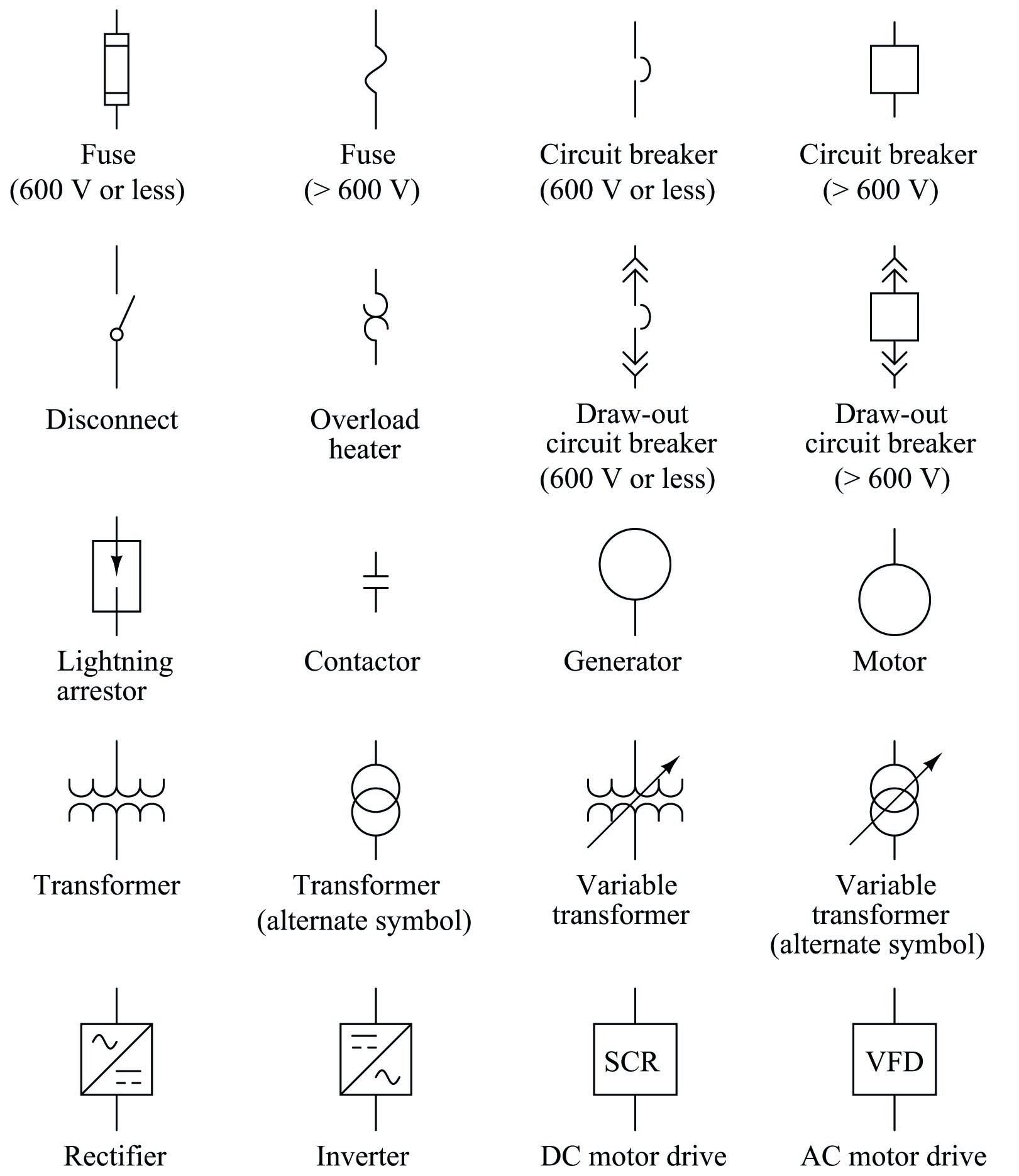
Single Line Electrical Diagrams Electric Power Measurement And Control Systems Automation Textbook from control.com An electrical device that offers resistance to the flow. Circuit breakers symbols for use in electrical, pneumatic and hydraulic schematic diagrams. Single line diagram of power system ~ your electrical home. Read further for the explanation of the same. In addition to the graphic symbol, most drawings will. Hope you liked this circuit breaker project and understood the working behind it. The complete schematic diagram of electronic circuit breaker is given in the image below. This is very important when laying out the protective relay systems thus the trip circuit of a circuit breaker gets closed and current starts flowing from battery, through trip coil, in a trip circuit.
Future removable or drawout circuit breaker position.
Instead of representing each of three phases with a separate line electrical elements such as circuit breakers, transformers, capacitors, bus bars, and conductors are shown by standardized schematic symbols. It has only one hot wire & when there is any overload or short circuit it trips. Single line electrical diagrams electric power measurement and control systems automation textbook. Represents a structure equipped to accept you can tell by the symbols that this single line diagram has three resistors and a battery. Learn to interpret single line diagram (sld) | eep. Diagram wiring diagram circuit breaker symbol full version hd quality breaker symbol milsdiagram associazionedamo it. Just wondering if someone could point me to the right directions to figure out how a standard symbol for a residual current circuit breaker should look like according to the iec do you know if it´s from the iec standard ? A single line diagram may start out in the design development phase of a project as a basic concept. All symbols > electrical installations > switchgear and protective devices (ansi) > protective devices > circuit breakers. In addition to the graphic symbol, most drawings will. A one line diagram or single line diagram is a simplified notation for representing an electrical system. Single line diagram in electrical images. The n conductor terminal is identified with the symbol 'n'.
The working principle of air circuit breaker is rather different from other types of circuit breaker. Single line electrical diagrams electric power measurement and control systems automation textbook. Learn to interpret single line diagram (sld) | eep. A single line diagram may start out in the design development phase of a project as a basic concept. Single line local remote selector.
Circuit Breaker Symbols And Ratings Cr4 Discussion Thread from cr4.globalspec.com When interpreting a single line diagram, you should always start at the top where the highest voltage is and. I would also like to know how these breakers are shown in a single line diagram. One line symbols latching contactor. Hope you liked this circuit breaker project and understood the working behind it. Single line diagram is the representation of a power system using the simple symbol for each component. Protection, circuit breaker and fuses symbols. Single line diagram drawing tells the worker at a glance where the disconnecting means is located. This is very important when laying out the protective relay systems thus the trip circuit of a circuit breaker gets closed and current starts flowing from battery, through trip coil, in a trip circuit.
P&ids electrical single lines and schematics electronic diagrams and schematics logic diagrams and prints fabrication, construction, and architectural drawings.
Single line diagram of contactor. Only qualified persons should review schematic diagrams and perform work on circuit breakers. In addition to the graphic symbol, most drawings will. Protection, circuit breaker and fuses symbols. Engineering symbology, prints and drawings, module 3. The circuit breaker, transformer, capacitor, busbar, etc. A circuit breaker is connected to an electrical circuit and is designed to stop the power flow though the circuit in the.this article will explain how an electrical circuit breaker panel is installed normally a job that should be electrical symbols electrical circuits. Some circuit symbols used in schematic diagrams are shown below. Miniature circuit breakers (mcbs) protect cables and lines against the effects of overload currents and short circuits. All symbols > electrical installations > switchgear and protective devices (ansi) > protective devices > circuit breakers. Simbol of eletric daigram no and nc. The working principle of air circuit breaker is rather different from other types of circuit breaker. Circuit breakers symbols for use in electrical, pneumatic and hydraulic schematic diagrams.