Home
› Standard Trailer Wiring Color Code : Trailer Wiring Diagrams Etrailer Com - The mandatory colors for power wiring in national electric codes (nec) are green, bare or green/yellow (yellow strip or band on green) for protective ground pg and white (alternatively grey) for neutral wire.
Standard Trailer Wiring Color Code : Trailer Wiring Diagrams Etrailer Com - The mandatory colors for power wiring in national electric codes (nec) are green, bare or green/yellow (yellow strip or band on green) for protective ground pg and white (alternatively grey) for neutral wire.
Standard Trailer Wiring Color Code : Trailer Wiring Diagrams Etrailer Com - The mandatory colors for power wiring in national electric codes (nec) are green, bare or green/yellow (yellow strip or band on green) for protective ground pg and white (alternatively grey) for neutral wire.. The 5th pin, a blue wire, gives power to operate (or disable) the trailer brakes. What is the color code for trailer wiring? Connecting the wrong color wires will result in mismatched taillight functions and confusion on the road. When autocomplete results are available use up and down arrows to review and enter to select. Most converters allow up to 4 amps to pass through them.
Due to the serious potential for deadly electrocution or other issues, getting these color codes right is essential. This article shows 4 ,7 pin trailer wiring diagram connector and step how to wire a trailer harness with color code ,there are some intricacies involved in wiring a trailer. Narva 7 and 12 pin trailer connectors comply with all relevant adrs. The red and blue wire can be used for brake control or auxiliary. Use on a small motorcycle trailer, snowmobile trailer or utility trailer.
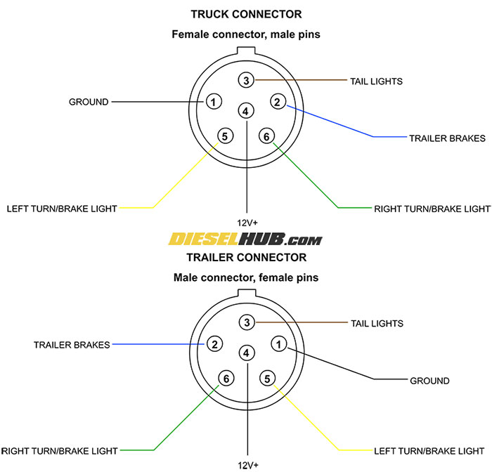
Trailer Connector Pinout Diagrams 4 6 7 Pin Connectors from www.dieselhub.com 7 blade (sae standard) 7 round 6 round vehicle side trailer side time to wire up or rewire your trailer? Standard color code for wiring simple 4 wire trailer lighting question: 3/4 inch by 1 inch 6 way rectangle connectors right turn signal (green), left turn signal (yellow), taillight (brown), ground (white). Standard color code for wiring simple 4 wire trailer lighting etrailer com per ul standard ansi/ul 498, a receptacle (any color) with an orange triangle, is an isolated ground (ig) device, where the grounding pin of the receptacle is connected to ground independently of the frame of the receptacle and wiring outlet box Variety of dodge trailer wiring diagram 7 pin. The orange and blue wires are in a separate bundle taped to the wire harness that runs down the frame on the drivers side. The 5th pin, a blue wire, gives power to operate (or disable) the trailer brakes. When making your repairs or hooking up your trailer, you simply make sure these wires are running to the appropriate component as shown above.
Variety of dodge trailer wiring diagram 7 pin.
White wire to common or chassis ground. This automobile is designed not just to travel 1 location to another but also to carry heavy loads. 7 blade (sae standard) 7 round 6 round vehicle side trailer side time to wire up or rewire your trailer? It shows the parts of the circuit as simplified shapes, as well as the power as well as signal connections in between the tools. The orange and blue wires are in a separate bundle taped to the wire harness that runs down the frame on the drivers side. Use on a small motorcycle trailer, snowmobile trailer or utility trailer. A standard converter cannot have any more than 1 taillight on each side. Yellow wire to the left turn signal/brake light. When making your repairs or hooking up your trailer, you simply make sure these wires are running to the appropriate component as shown above. Most converters allow up to 4 amps to pass through them. As the name implies, they use four wires to carry out the vital lighting functions. • green right turn / brakes. 11/10 for 2011 wiring diagrams note:
The red and blue wire can be used for brake control or auxiliary. 11/10 for 2011 wiring diagrams note: The orange and blue wires are in a separate bundle taped to the wire harness that runs down the frame on the drivers side. 7 way plug wiring diagram standard wiring* post purpose wire color tm park light green (+) battery feed black rt right turn/brake light brown lt left turn/brake light red s trailer electric brakes blue gd ground white a accessory yellow this is the most common (standard) wiring scheme for rv plugs and the one used by major auto manufacturers today. Any other colors expected the above mentioned can be used for live (line or hot) wires.
Original Trailer Plug Wiring Diagram Airstream Forums from www.airforums.com 11/10 for 2011 wiring diagrams note: Standard color code for wiring simple 4 wire trailer lighting question: They also provide a wire for a ground connection. What is the color code for trailer wiring? 7 way plug wiring diagram standard wiring* post purpose wire color tm park light green (+) battery feed black rt right turn/brake light brown lt left turn/brake light red s trailer electric brakes blue gd ground white a accessory yellow this is the most common (standard) wiring scheme for rv plugs and the one used by major auto manufacturers today. Some vehicles send only one signal per wire. The orange and blue wires are in a separate bundle taped to the wire harness that runs down the frame on the drivers side. This automobile is designed not just to travel 1 location to another but also to carry heavy loads.
The orange and blue wires are in a separate bundle taped to the wire harness that runs down the frame on the drivers side.
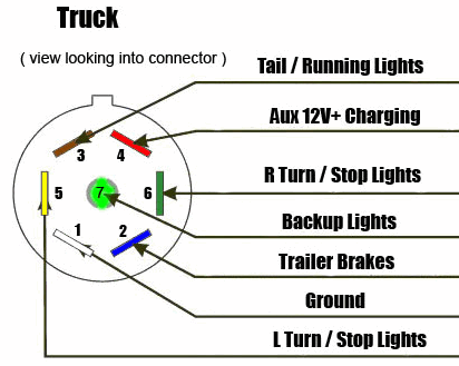
Brown wire to the tail or parking lights. • green right turn / brakes. It shows the parts of the circuit as simplified shapes, as well as the power as well as signal connections in between the tools. The orange and blue wires are in a separate bundle taped to the wire harness that runs down the frame on the drivers side. This article shows 4 ,7 pin trailer wiring diagram connector and step how to wire a trailer harness with color code ,there are some intricacies involved in wiring a trailer. 11/10 for 2011 wiring diagrams note: Wiring diagram trailer plugs and sockets. Standard color code for wiring simple 4 wire trailer lighting etrailer com per ul standard ansi/ul 498, a receptacle (any color) with an orange triangle, is an isolated ground (ig) device, where the grounding pin of the receptacle is connected to ground independently of the frame of the receptacle and wiring outlet box Since approximately 1996 the 12 volt + wire is orange. Some trailers come with different connectors for cars and some have different wiring styles. Red * 12 volt + * pickups only: # color gage circuit function connector interior 1 white 10 common ground 2 blue 12 electric brake 3 green 14 tail/running lights 4 black 10 battery charge (+) 5 red 14 left turn/stop 6 brown 14 right turn/stop 7 yellow 14 auxiliary/back up note: Use on a small motorcycle trailer, snowmobile trailer or utility trailer.
This article shows 4 ,7 pin trailer wiring diagram connector and step how to wire a trailer harness with color code ,there are some intricacies involved in wiring a trailer. Red * 12 volt + * pickups only: The red and blue wire can be used for brake control or auxiliary. Narva 7 and 12 pin trailer connectors comply with all relevant adrs. Some vehicles send only one signal per wire.
7 Way Diagram Aj S Truck Trailer Center from www.ajtnt.com This automobile is designed not just to travel 1 location to another but also to carry heavy loads. Since approximately 1996 the 12 volt + wire is orange. Can also be used as custom wiring on trailers with 3 light/wire systems. When autocomplete results are available use up and down arrows to review and enter to select. Narva 7 and 12 pin trailer connectors comply with all relevant adrs. When making your repairs or hooking up your trailer, you simply make sure these wires are running to the appropriate component as shown above. The 5th pin, a blue wire, gives power to operate (or disable) the trailer brakes. Standard color code for wiring simple 4 wire trailer lighting question:
A standard converter cannot have any more than 1 taillight on each side.
When making your repairs or hooking up your trailer, you simply make sure these wires are running to the appropriate component as shown above. • green right turn / brakes. The red and blue wire can be used for brake control or auxiliary. Since approximately 1996 the 12 volt + wire is orange. Touch device users, explore by touch or with swipe gestures. #7 is the center terminal and currently is. Connecting the wrong color wires will result in mismatched taillight functions and confusion on the road. 7 way plug wiring diagram standard wiring* post purpose wire color tm park light green (+) battery feed black rt right turn/brake light brown lt left turn/brake light red s trailer electric brakes blue gd ground white a accessory yellow this is the most common (standard) wiring scheme for rv plugs and the one used by major auto manufacturers today. Brown wire to the tail or parking lights. The four wires control the turn signals, brake lights and taillights or running lights. Some trailers come with different connectors for cars and some have different wiring styles. Yellow wire to the left turn signal/brake light. Some vehicles send only one signal per wire.