Home
› Wiring Diagram Definition : Age Structure Diagram Definition Biology - General Wiring Diagram - These diagrams provide the quickest path to success when dealing with complex electrical problems on any vehicle.
Wiring Diagram Definition : Age Structure Diagram Definition Biology - General Wiring Diagram - These diagrams provide the quickest path to success when dealing with complex electrical problems on any vehicle.
Wiring Diagram Definition : Age Structure Diagram Definition Biology - General Wiring Diagram - These diagrams provide the quickest path to success when dealing with complex electrical problems on any vehicle.. Wiring diagrams are drawings of electronic systems found in high quality workshop repair manuals. A wiring diagram is a simplified conventional pictorial representation of the physical connections and physical layout of an electrical system or circuit. Connect the lead wire that is to be connected to sinpac switch terminal #2 securely to the lead wire that is to be connected to sinpac switch terminal #3. Electrical schematic diagram | elementary & wiring diagram electrical schematic diagrams convey specific information to the technician. The process of boosting an electrical signal is.
An amplifier is an electronic circuit used to boost up the strength of the weak signal. Sometimes wire diagrams can closely represent a picture. You can expand the same conditions for more axles. It is a 2 port circuit that increases the amplitude of the input signal and provides an amplified signal at the output end. The process of boosting an electrical signal is.
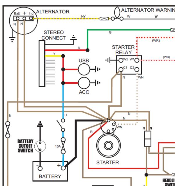
CS130 Alternator - Extra Wire Definition : MGB & GT Forum : MG Experience Forums : The MG Experience from www.mgexp.com A diagram that uses lines to represent the wires and symbols to represent components. You can expand the same conditions for more axles. The power supply is shown at the top and the earth at the bottom to facilitate understanding of the current flow. Electrician circuit drawings and wiring diagrams youth explore trades skills 3 pictorial diagram: Basics 13 valve limit switch legend : A diagram that represents the elements of a system using abstract, graphic drawings or realistic pictures. These diagrams provide the quickest path to success when dealing with complex electrical problems on any vehicle. Wiring diagrams show how the aircraft wires are connected and where they should be located in the electrical system, as well as the physical connections between all the components.
The wiring diagram shows different components in a circuit via different shapes and symbols.
It shows the components of the circuit as simplified shapes, and the power and signal connections between the devices. The third and last type of diagram is the installation diagram. Basics 13 valve limit switch legend : How to use wiring in a sentence. Vertical and horizontal lines are used to represent wires and each line represents a single wire that connects between electrical components. It shows how the electrical wires are interconnected and can also show where fixtures and components may be connected to the system. They illustrate such items as the size, type, component part number, and component location in relationship to the other circuit components. A wiring diagram is simply a pictorial representation of all the electrical connections in a specific circuit. The power supply is shown at the top and the earth at the bottom to facilitate understanding of the current flow. The process of boosting an electrical signal is. These diagrams are an effective way of showing how wires are interconnected with different components in a system. A wiring diagram usually gives information not quite the relative tilt and deal of devices and. Figure 3 is a typical installation diagram for a residential cooling system.
The 2 above wire diagrams fit the needs of most trailers. It shows how the electrical wires are interconnected and can also show where fixtures and components may be connected to the system. Wiring diagram a wiring diagram, shown in figure 1, is an electrical print that shows connections of all components in a piece of equipment. Unlike a schematic, it's concerned with the connections between the different parts of a circuit or parts of an entire electrical system. Circuit diagram a circuit diagram is a simplified conventional graphical representation of an electrical circuit.
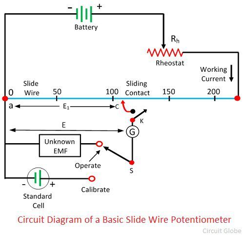
What is Potentiometer (POT)? - Definition, Characteristics, Construction & Working - Circuit Globe from circuitglobe.com The third and last type of diagram is the installation diagram. It normally shows only what the terminal board connections are, and very rarely will it include any internal wiring of the unit. Wiring diagram a wiring diagram, shown in figure 1, is an electrical print that shows connections of all components in a piece of equipment. Figure 3 is a typical installation diagram for a residential cooling system. When and how to use a wiring diagram Secure the motor to a firm mounting surface. These diagrams are an effective way of showing how wires are interconnected with different components in a system. A wiring diagram is a simplified conventional pictorial representation of the physical connections and physical layout of an electrical system or circuit.
Schematic schematic drawing diagram of an electrical or mechanical system.
Basics 13 valve limit switch legend : This is a little complicated form of block diagram but simpler than a circuit diagram; A wiring diagram is simply a pictorial representation of all the electrical connections in a specific circuit. Typical trailer wiring diagram and schematic. The 2 above wire diagrams fit the needs of most trailers. Unlike a schematic, it's concerned with the connections between the different parts of a circuit or parts of an entire electrical system. A diagram that represents the elements of a system using abstract, graphic drawings or realistic pictures. The power supply is shown at the top and the earth at the bottom to facilitate understanding of the current flow. A wiring diagram is a simple visual representation of the physical connections and physical layout of an electrical system or circuit. 1991 chevy truck wiring diagram. A wiring diagram usually gives information not quite the relative tilt and deal of devices and. It normally shows only what the terminal board connections are, and very rarely will it include any internal wiring of the unit. Prepare the motor wiring for connection of the sinpac switch as shown in the wiring diagrams for sinpac switches section of this publication.
The 2 above wire diagrams fit the needs of most trailers. It shows the components of the circuit as simplified shapes, and the skill and signal connections surrounded by the devices. Wiring diagram a wiring diagram, shown in figure 1, is an electrical print that shows connections of all components in a piece of equipment. The wiring diagram is used for the representation of electrical components in their approximate physical location using their specific symbols and their interconnections using lines. The power supply is shown at the top and the earth at the bottom to facilitate understanding of the current flow.
Electrical Engineering World: The Practical Way of Wiring the Three Phase 60A Distribution Board ... from 2.bp.blogspot.com The 2 above wire diagrams fit the needs of most trailers. It is a 2 port circuit that increases the amplitude of the input signal and provides an amplified signal at the output end. You can expand the same conditions for more axles. Wiring diagram a wiring diagram, shown in figure 1, is an electrical print that shows connections of all components in a piece of equipment. Only the (blue) brake and (white) ground wires are different. A wiring diagram is a simple visual representation of the physical connections and physical layout of an electrical system or circuit. Basics 10 480 v pump schematic : The third and last type of diagram is the installation diagram.
Wiring diagrams show, as closely as possible, the actual location of each component in a circuit, including the control circuit and the power circuit.
A diagram that uses lines to represent the wires and symbols to represent components. Electrical schematic diagram | elementary & wiring diagram electrical schematic diagrams convey specific information to the technician. Wiring diagrams tend to show a close representation of the interior position of electrical components in a control cabinet and/or circuit. Basics 14 aov schematic (with block included) basics 15 wiring (or connection. This signal can be a current, voltage or power signal. This is a tool that is used primarily by the installing contractor. The usage of wiring diagram These diagrams are an effective way of showing how wires are interconnected with different components in a system. Wiring diagram a wiring diagram, shown in figure 1, is an electrical print that shows connections of all components in a piece of equipment. Wiring diagrams are drawings of electronic systems found in high quality workshop repair manuals. It normally shows only what the terminal board connections are, and very rarely will it include any internal wiring of the unit. The process of boosting an electrical signal is. Prepare the motor wiring for connection of the sinpac switch as shown in the wiring diagrams for sinpac switches section of this publication.