Full Subtractor Logic Diagram And Truth - Mantra VLSI : full subtractor / Full subtractor combinational logic circuits electronics tutorial.. Draw truth table and logic diagram of full subtractor. For example b and c in my case. Fugure below shows the block diagram of the full subtractor. Logic diagram for a half subtractor. Full subtractor definition, block diagram, truth table, circuit diagram, logic diagram, boolean expression and equation are discussed.
Full subtractor overcomes the limitation of half subtractor. The logic symbol of half subtractor is represented in the diagram below. Logic diagram for a half subtractor. The half subtractors designed can be used in the the subtractor designed by logic gates is described below. The truth table of this subtractor consists of the values of minuend (a), subtrahend (b) and the borrow.
Half Subtractor and Full Subtractor | FlintGroups from 1.bp.blogspot.com The half subtractor produces a difference and a borrow bit for the next stage. The block diagram of a half subtractor is shown below in fig.1. The full subtractor is a combinational circuit which is used to perform subtraction of three input bits: Select 2 variables as your select line. Minuend, subtrahend and a borrow bit and it produces two outputs: The circuit is assembled as per the circuit diagram. Start with the truth table of full subtractor. Full subtractor definition circuit diagram truth table.
Hexadecimal display is also connected to output.
662 249 просмотров 662 тыс. The logic diagram of full subtractor is shown below. Schematic diagrams of full adders. The half subtractors designed can be used in the the subtractor designed by logic gates is described below. Hexadecimal display is also connected to output. Full subtractor in digital logic geeksforgeeks. Dip switches and resistors are connected to the inputs and led's are connected to the outputs. The circuit is assembled as per the circuit diagram. Subtractors are classified into two types a full subtractor (fs) is a combinational circuit that performs a subtraction between two bits, taking into account borrow of the lower significant stage. A subtractor is a digital logic circuit in electronics that performs the operation of subtraction of two number. Subtractor is the one which used to subtract two binary number(digit) and provides difference and borrow as a output.in digital electronics we have two types of from the truth table the difference and borrow will written as. The full subtractor generates two output bits: Full subtractor performs subtraction of two bits, one is minuend and other is subtrahend.
Fugure below shows the block diagram of the full subtractor. Adders & subtractors are wildly used in in computer's alu (arithmetic logic unit) to compute addition as well as cpu (central processing unit) and gpu (graphics processing unit) for graphics applications to reduce the circuit. Makes no sense at all. Design half subtractor and full subtractor in verilog hdl. The half subtractors designed can be used in the the subtractor designed by logic gates is described below.
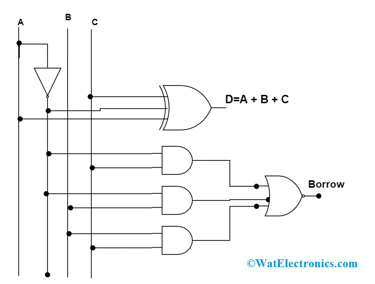
Combinational Logic Circuits : Definition, Examples, and Applications from www.watelectronics.com Full subtractor is a combinational circuit that perform subtraction of three input bits namely minuend bit a, subtrahend bit b, and borrow in c. Hexadecimal display is also connected to output. The block diagram of a half subtractor is shown below in fig.1. Classece6332spring17alu uva ece bme wiki. Full subtractor is a combinational logic circuit used for the purpose of subtracting two single bit numbers with a borrow. There are two types of subtractors. Subtractor circuits take two binary numbers as input and subtract one binary number input from the other binary number input. The logic symbol of half subtractor is represented in the diagram below.
Classece6332spring17alu uva ece bme wiki.
A subtractor is a digital logic circuit in electronics that performs the operation of subtraction of two number. A full subtractor subtracts two bits a from b, along with previous borrow bin. Full subtractor | easy explanation. For example b and c in my case. Power of 5v is applied at. The half subtractors designed can be used in the the subtractor designed by logic gates is described below. Full subtractor in digital logic geeksforgeeks. Full subtractor circuit diagram with logic gates the circuit diagram of full subtractor employing basic gates is proven in the below given block full subtractor truth table. The full subtractor is a combinational circuit which is used to perform subtraction of three input bits: And full subtractor in simulator 2. You can see that the output s is an xor between the implementation of larger logic diagrams is possible with the above full adder logic a simpler symbol is mostly used to represent the operation. The block diagram of a half subtractor is shown below in fig.1. The full subtractor generates two output bits:
Subtractor is the one which used to subtract two binary number(digit) and provides difference and borrow as a output.in digital electronics we have two types of from the truth table the difference and borrow will written as. And full subtractor in simulator 2. There are two types of subtractors. This article is contributed by harshita pandey. Hexadecimal display is also connected to output.
Digital Logic Design: Full Subtractor Circuit from 1.bp.blogspot.com Full subtractor is a combinational circuit that perform subtraction of three input bits namely minuend bit a, subtrahend bit b, and borrow in c. For example b and c in my case. Full subtractor overcomes the limitation of half subtractor. Fugure below shows the block diagram of the full subtractor. Binary subtractor.the block model, truth table and logic diagram of a half subtractor shown in above figure.acquista per non rimanere deluso.in this implementation, carry of each full adder is connected. A full subtractor subtracts two bits a from b, along with previous borrow bin. Subtractor circuits take two binary numbers as input and subtract one binary number input from the other binary number input. Makes no sense at all.
A half subtractor is a logical circuit that performs a subtraction operation on two binary digits.
By using any full subtractor logic circuit. The half subtractors designed can be used in the the subtractor designed by logic gates is described below. Hexadecimal display is also connected to output. In the above image, instead of block diagram, actual symbols are shown. Full subtractor performs subtraction of two bits, one is minuend and other is subtrahend. Theory subtractor circuits take two binary numbers as input and subtract one binary number input from the other it accepts three inputs: Full subtractor is a combinational logic circuit used for the purpose of subtracting two single bit numbers with a borrow. This is executed till 100 ns, which is the the logic diagram includes an and gate and two half subtractor circuits, which are further an or, xor. A subtractor is a digital logic circuit in electronics that performs the operation of subtraction of two number. Full subtractor is a combinational circuit that perform subtraction of three input bits namely minuend bit a, subtrahend bit b, and borrow in c. Previously, we have discussed an overview of this like construction, circuit diagram with logic gates. Binary addition and subtraction.logic diagram for full subtractor.full adder logic diagram. Select 2 variables as your select line.